Horizontal Fire Resistance Test Furnace
BS 476 (20-24); BS EN 1363 (1-2); BS EN 1364 (2); BS EN 1365 (2-4); BS EN 1366 (1-3); ASTM E119; ASTM E814; ASTM E1966; UL 263; UL 1709; UL 1479; UL 2079; UL10 (B-C); ISO 834 (1, 5-7, 9); ISO 6944 (1-2); ISO 3008
The fire resistance of a material forming part of an assembly is an invaluable tool in assessing the performance of construction elements relied upon in regulations.
The FTT Horizontal Fire Resistance Test Furnace is the apparatus needed to evaluate the fire resistance of a horizontal construction assembly, column, or support, and provides a method of quantifying the ability of a material, in a horizontal orientation, to withstand exposure to high temperatures. This is done by evaluating a number of performance elements such as the load-bearing capacity, the ability to provide fire containment and the thermal transmittance of the materials and systems.
- The capability to carry out both load-bearing and non-load bearing tests on horizontal test specimens and beams that are mounted in customised restraint frames.
- Superior and safe construction – furnace walls comprising a lining of insulating fire bricks, refractory castables and mineral fibre board on the cold face and refractory insulating bricks anchored back to the wall with high temperature cast in situ blocks, on the hot face.
- A removable roof lined with profiled bricks and anchored with refractories cast in situ.
- A furnace casing made of mild steel plates reinforced with steel C-Channels, I-beams and steel sections to counter structural distortion due to heat.
- A specimen restraint frame secured by a minimum of 4 sets of clamps.
- 4 viewing ports made of heat resistant quartz glass to enable the operator to view the complete test specimen during a fire test.
- A sliding door made of lightweight alumina is enclosed within an insulated, air-cooled frame. This will shield off the furnace heat when the viewing ports are not in use.
- 20 sets of Refractory Nozzle Mix Burners (2 groups of 10). Each burner is designed to use liquefied petroleum gas and has a flame supervision unit to ensure that all combustion units operate on a fail safe mode at all times. All necessary flame safety systems, intermittent pilot systems, and temperature sensors are incorporated.
- A Furnace Combustion Control Panel is designed to operate on both fully automatic and manual control modes. Automatic ignition of the burners is through the use of one push button switch. This fires up the burners based on a preset heating curve, such as that described in BS 476 Parts 20-24, EN 1363 and the IMO Hydrocarbon Curve. Manual burner control enables individual burners to be ignited at will.
- Test area dimensions: 3000mm (W) × 4000mm (H) × 1000mm (D)
Horizontal Fire Resistance Test Furnace
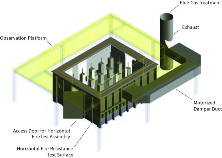
Fire Resistance Test Furnaces system diagram